Effect of building geometrical features on the development of externally venting flames
By: Anoop Warrier, Khalid Khan, Nasriani Hamid, Shephard Ndlovu, Tony Graham, Eleni Asimakopoulou, University of Central Lancashire, UK
This work has been partially funded by SFPE Foundation as Anoop Warrier received the November 2022 SFPE Foundation Student Research Grant.
Introduction
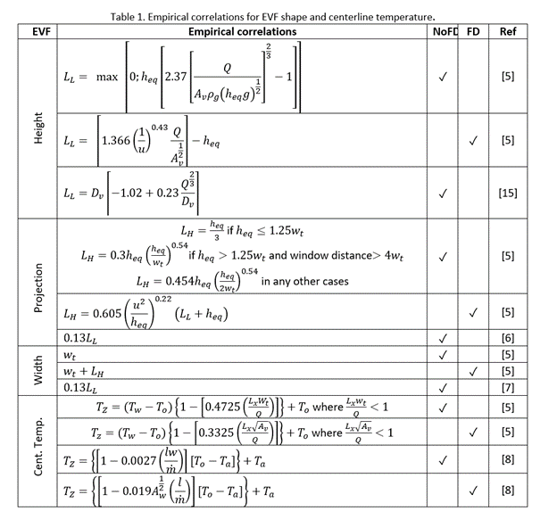
The building industry is increasingly favoring green building initiatives resulting in increased use of different façade materials and systems. This has highlighted the need to address the relevant fire-safety challenges of green buildings as recently there has been an increased number of façade fires around the world [1, 2]. Externally venting flames (EVF) refers to the flames and hot combustion products ejecting through windows and openings aided by buoyancy when the compartment fire is either in under or well-ventilated conditions [3]. EVF increases the risk of external flame spread and have a great impact on the fire spread through the building envelope to different storeys but also to adjacent buildings, especially for high-rise buildings [4]. New engineering technologies and advanced manufacturing techniques have enabled the construction of new façade systems, e.g., curved glass façade systems. Further, non-orthogonal, curvilinear or “free-form” geometries are widely used in building façade designs, and they pose a significant challenge for the fire safety design of the building as the emphasis on aesthetics many a times results in the use of non-conventional building materials which aggravates and enhances the fire spread in such constructions [4]. Most widely used correlations to estimate EVF thermal and geometrical characteristics are presented in Table 1. Though there has been a multitude of studies on facade fires in orthogonal or rectilinear geometries, the influence of non-orthogonal geometry upon the EVF is not thoroughly investigated. The aim of this work is to increase understanding of EVF development in curvilinear geometries using numerical and empirical correlations to investigate the influence of geometry, ventilation and heat release rate.
Methodology
The Fire Dynamic Simulator (FDS, Version 6.7.6) was used for the current study to perform the Computational Fluid Dynamics (CFD) simulations [9]. The study was conducted in two different geometries constructed with steel, the schematic views of which are depicted in Figure 1. Geometry 1 has a curvilinear shape with a length of 4.4 m, a width of 4 m, and a height of 3 m from floor level to the top. To keep a similar volume for the comparative study, geometry 2 has the same plan dimensions as that of geometry 1, with rectilinear elevation, and is provided with a height of 2.7 m.

Fig. 1. Geometry and location of measuring devices, all dimensions are in mm.
To study the influence of ventilation condition on EVF development in these geometries, the compartment is provided with 2 equal sized openings on either side of the wall with a width of 1.1 m and height of 2 m to facilitate “Forced Draught” conditions (FD) and to simulate “No Forced Draught” condition (NoFD), the geometry is restricted to a single opening as seen in Figure 2. Measuring devices are set up in the numerical model to measure temperature and heat flux on the façade walls of the geometries.
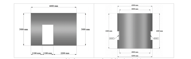
Fig. 2. Openings of the fire compartment front (left) and top (right) view.
A parametric study has been conducted with varying Heat Release Rate (HRR) of 1.5 MW, 2 MW, 3 MW and 4 MW and with two ventilation conditions in both curvilinear and rectilinear geometries. A burner with size 0.9 m x 0.9 m x 0.15 m was positioned at the geometrical center of the compartment and a total of 16 different simulation cases were considered to investigate the EVF thermal and geometrical characteristics for comparison.
The fire compartments comprised of two equal sized openings on either side of the wall with a 1.1 m width and 2 m height. To replicate NoFD and FD conditions, two ventilations modes were simulated. Fig. 2 (right) is a top view the fire compartment with two equal sized openings on opposite walls of the compartment which will facilitate FD conditions, namely Door 1 and Door 2. All solid surfaces, including walls and floors, are provided with boundary condition with following material properties corresponding to steel, e.g., 7850 kg/m3 density, 0.46 kJ/(kg K) specific heat, 0.02 m thickness, and emissivity of 0.95. The soot yield, which represents the fraction of heptane fuel mass converted to smoke particulates, is set equal to 0.015 kg/kg and the corresponding CO yield was set equal to 0.006 kg/kg. The D*/dx ratio of 16 was found to be the most optimal with a corresponding cell size of 0.07 m. These values enable adequate resolution of plume dynamics and other geometric characteristics of the model [10]. The total computational grid consists of 716,958 cubic cells for NoFD and 963,186 cubic cells for FD conditions. The numerical investigation for both models assumed ambient conditions and an ambient temperature of 40oC. Aiming to investigate the effect of ventilation conditions and fuel load on the development of an EVF from a curvilinear fire compartment, a set of relevant numerical test cases have been chosen. As indicated in Table 2, sixteen numerical cases were used to investigate the effect of NoFD and FD conditions and a parametric study has been conducting by varying the HRR using 1.5 MW, 2 MW and 4 MW fires. in the Table 2.
Table 2. Examined numerical cases.
|
Case
|
Geometry-1
|
Geometry-2
|
Ventilation
|
Door 1
|
Door 2
|
HRR
|
|
NoFD-1.5-G2
|
|
✓
|
NoFD
|
✓
|
N/A
|
1.5 MW
|
|
NoFD-2.0-G2
|
|
✓
|
✓
|
N/A
|
2.0 MW
|
|
NoFD-3.0-G2
|
|
✓
|
✓
|
N/A
|
3.0 MW
|
|
NoFD-4.0-G2
|
|
✓
|
✓
|
N/A
|
4.0 MW
|
|
NoFD-1.5-G1
|
✓
|
|
✓
|
N/A
|
1.5 MW
|
|
NoFD-2.0-G1
|
✓
|
|
✓
|
N/A
|
2.0 MW
|
|
NoFD-3.0-G1
|
✓
|
|
✓
|
N/A
|
3.0 MW
|
|
NoFD-4.0-G1
|
✓
|
|
✓
|
N/A
|
4.0 MW
|
|
FD-1.5-G2
|
|
✓
|
FD
|
✓
|
✓
|
1.5 MW
|
|
FD-2.0-G2
|
|
✓
|
✓
|
✓
|
2.0 MW
|
|
FD-3.0-G2
|
|
✓
|
✓
|
✓
|
3.0 MW
|
|
FD-4.0-G2
|
|
✓
|
✓
|
✓
|
4.0 MW
|
|
FD-1.5-G1
|
✓
|
|
✓
|
✓
|
1.5 MW
|
|
FD-2.0-G1
|
✓
|
|
✓
|
✓
|
2.0 MW
|
|
FD-3.0-G1
|
✓
|
|
✓
|
✓
|
3.0 MW
|
|
FD-4.0-G1
|
✓
|
|
✓
|
✓
|
4.0 MW
|
Results
In compartments with curvilinear geometry under both FD and NoFD conditions smoke movement can be a complex fire dynamic process due to the interaction of turbulence, combustion, and radiation with the geometry of the compartment [11]. The relevant flow field for the most increased HRR NoFD-4.0-G2, FD-4.0-G2, NoFD-4.0-G1 and FD-4.0-G1 cases are depicted in Figure 3. A clear circulation zone is evident in all NoFD cases, but for the curvilinear compartment, NoFD-4.0-G1, the flow is closely attached to the solid curved boundaries of the compartment when compared with the rectilinear walls and velocity field is more intense with peak velocities at a range of 8.5 m/s. Under FD conditions, a more rigorous and intense mixing of cold air from both side of the compartment openings occurs and results in the formation of two recirculation zones inside both rectilinear and curvilinear compartments ensuing a more turbulent flow which owes to the higher velocity and high Reynolds number of the incoming flow; in the FD-4.0-G2 case, EVF velocities are higher. 
Fig. 3. Gas mixture velocity 500 s after fire initiation for NoFD (top) and FD (bottom) conditions for both rectilinear (left) and curvilinear (right) 4 MW cases.
For 1.5 MW, 2.0 MW and 4.0 MW Geometry 1 cases, characteristic contours of the temperature field 500 s after fire initiation under FD and NoFD conditions are depicted in Figure 4. The maximum temperature distribution is observed for case NoFD-4.0-G1, after 10 seconds of fire initiation, where a clear stratification of hot and cold layer inside the compartment and a transient increase in temperature with respect to height. Following this, an increase in the volume of hot upper layer and larger volume of unburned gas flows out in the exterior domain forming larger EVF and a stronger buoyant plume. It is important to note that as the plume further goes up, the EVF temperature decreases with respect to the height. At 500 s after the fire initiation, a clear division of hot and cold layer can be seen at the interior of the compartment for the case of FD condition whereas the separation of hot and cold layer is no longer visible in NoFD where a well-mixed layers of hot gases is sustained. Under NoFD conditions higher temperature ranges are observed.
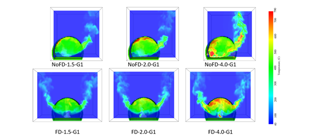
Fig. 4. Spatial distribution of gaseous temperature 500 s after fire initiation for the 1.5MW. 2.0 MW and 4.0 MW Geometry 1 cases under FD and NoFD conditions.
To quantify the geometric characteristics of the EVF envelope, a digital image processing tool using MATLAB code has been developed, and in all cases aiming to determine the geometric characteristics of the EVF envelope. The calculated spatial distribution of flame envelope probability, expressed via the flame intermittency, is illustrated in Figure 5. Mean flame height for these cases has been determined, which demonstrates that geometrical features, ventilation, and heat release rate having an influence on the development and geometric characteristics of EVF.
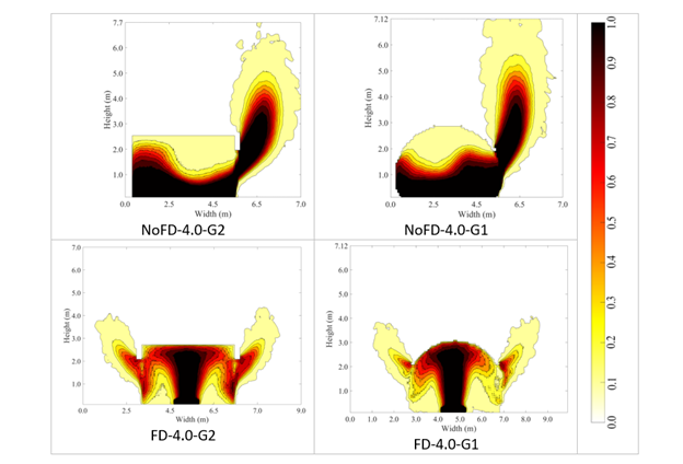
Fig. 5. Side view of the flame intermittency contours for NoFD (top) and FD (bottom) conditions for both rectilinear (left) and curvilinear (right) 4 MW cases.
Figure 6 shows the vertical distribution of the averaged centerline temperature at the exterior of the fire compartment for NoFD conditions for the rectilinear and curvilinear cases as calculated with EC1 and relevant predictions. EC1 methodology tends to over predict centerline temperatures for all rectilinear NoFD cases. Near to the opening a larger discrepancy is observed as EC1 results are twice the value of the numerical data. For lower HRR there is better agreement for the NoFD cases in rectilinear geometries especially at higher heights. This is not the case for NoFD conditions in curvilinear geometries, Figure 7, as in some cases, (1.5 MW, 2 MW and 4 MW), EC1 underpredicts values compared to predictions.
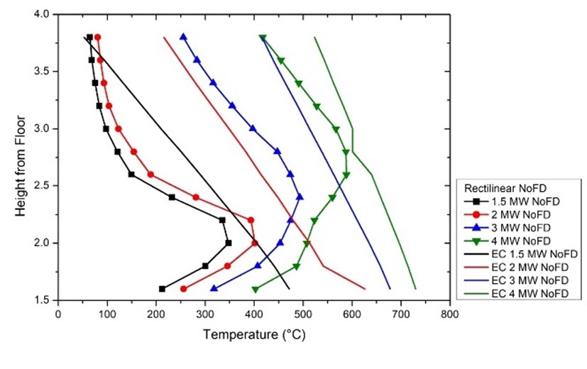
Fig. 6. Vertical distribution of the averaged centerline temperature at the exterior of the fire compartment for NoFD conditions for the rectilinear cases
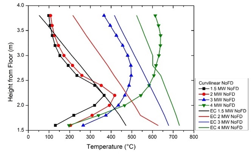
Fig. 7. Vertical distribution of the averaged centerline temperature at the exterior of the fire compartment for NoFD conditions for the curvilinear cases.
Conclusions
Predictions using the empirical correlations for the estimation of the EVF heigh (LL) and width (wf) were compared against the available empirical correlations. EC1 methodology for the estimation of LL for NoFD conditions were found to yield decreased EVF height for both rectilinear and curvilinear geometries compared to numerical data. For FD conditions both EC1 and Heskestad methodology seem to over-estimate EVF height compared to current predictions. Values of EVF width (wf) were found to strongly depend on both excess heat release rate from the compartment fire. Under NoFD conditions EC1 methodology shows a strong disagreement with numerical values as it underpredicts EVF width. Under FD conditions, for all geometries, EC1 methodology overestimates width compared to predictions. EC1 methodology tends to over predict centerline temperatures for all rectilinear NoFD cases. This is not the case for NoFD conditions in curvilinear geometries as in most of the cases EC1 underpredicts values compared to predictions. Obtained extensive set of numerical data, derived for the interior and exterior of the fire compartment will be further validated with experimental results in curvilinear geometries.
References
[1] E. Asimakopoulou, D. Kolaitis, M. Founti, Performance of a ventilated-façade system under fire conditions: An experimental investigation, Fire Mater. 44(6) (2020) 776-792.
[2] M. Bonner, W. Wegrzynski, B. Papis, G. Rein, KRESNIK: A top-down, statistical approach to understand the fire performance of building facades using standard test data, Building Environ 169 (2020) 106540.
[3] L. Hu, Z. Qiu, K. Lu, F. Tang, Window ejected flame width and depth evolution along façade from under-ventilated enclosure fires, Fire Safety J. 76 (2015) 44-53.
[4] N. White, M. Delichatsios, Fire hazards of exterior wall assemblies containing combustible components, first ed., Springer Briefs in Fire, Springer, New York, 2014.
[5] EN 1991-1-2, Eurocode 1: Actions on Structures, Part 1-2 – General Actions – Actions on Structures Exposed to Fire, European Committee for Standardization, Brussels, Belgium, 2002.
[6] S. Yokoi, Study on the prevention of fire-spread caused by hot upward current, BRI Report 34.,1960.
[7] D. Kolaitis, E. Asimakopoulou, M. Founti, Fire behaviour of gypsum plasterboard wall assemblies: CFD simulation of a full-scale residential building, Case Studies in Fire Safety 7 (2017) 23-35.
[8] M. Law, T. O’Brien, Fire safety of bare external structural steel, The Steel Construction Institute, SCI Publication 009, 1989.
[9] K. McGrattan, R. McDermott, M. Vanella, S. Hostikka, J. Floyd, R, Fire Dynamics Simulator User's Guide, 6th Edition, National Institute of Standards and Technology, 2022.
[10] K. McGrattan, S. Hostikka, J. Floyd, R. McDermott, M. Vanella, M., Fire Dynamics Simulator Technical Reference Guide Volume 2: Verification, NIST Special Publication 1018-2, 6th Edition, National Institute of Standards and Technology, 2022.
[11] W. Feng, W. Mingnian, C. Ricky, W. Yu., Numerical study on fire smoke movement and control in curved road tunnels. Tunn Undergr Space Technol 67 (2017) 1-7.