A Simplified Method for Calculation of Coat Back Lengths
By: Arnoud Breunese, Promat Product Manager/Etex, Netherlands
Whenever non-loadbearing steel members (“attachments”) are attached to a loadbearing steel (“primary”) member and penetrate its passive fire protection, additional heat will be conducted to the primary member during a fire. This will result in a local hot spot in the primary member that may reduce the actual fire resistance. Finite element simulations for realistic geometries show that the critical steel temperature (i.e. the supposed failure temperature of the steel member) is reached between 20% and 80% sooner than the design situation. Structural failure is generally directly linked to the location with the highest temperature because this is the weakest link of the structural system. In other words, leaving steel attachments unprotected is likely to reduce the fire resistance time of the primary member by 20% to 80%. The wide variation in this percentage is due to the fact that geometries can vary, and in particular the dimensions of the attachments are of influence.
In order to avoid that the fire resistance is strongly reduced, coat backs must be applied: passive fire protection is also applied on the attachment over a certain length from the connection to the primary member. In onshore oil & gas structures coat backs are often omitted, due to the lack of clear rules and calculation methods and possibly a lack of awareness of the importance for the overall passive fire protection performance.
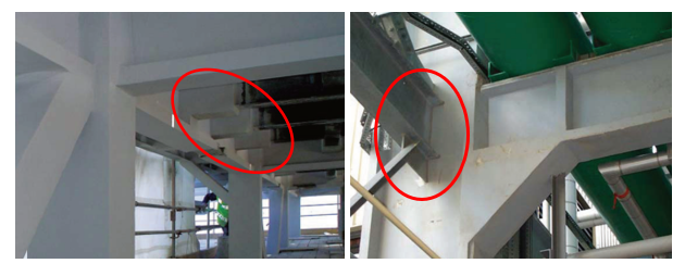
Figure 1: example of coat backs in practice (left) and no coat back (right)
Thermal effects around a coat back
The temperature distribution around an attachment with coat back is highly complex. It is defined by the interaction of different heat paths:
- Heat flow through the steel attachment, in its longitudinal direction, from the unprotected area towards the primary member,
- Heat flow through the coat back fire protection of the attachment, causing the attachment to heat up and therefore also conducting heat to the primary member,
- Design situation for the fire protection thickness: heat flow through the fire protection of the primary member (without considering the attachment).
- Heat flow away from the attachment, through the primary member in the sectional plane
- Heat flow away from the attachment, through the primary member in longitudinal direction
- Local effect at the connection where the fire protection forms a corner (from primary member to attachment), locally providing additional protection.
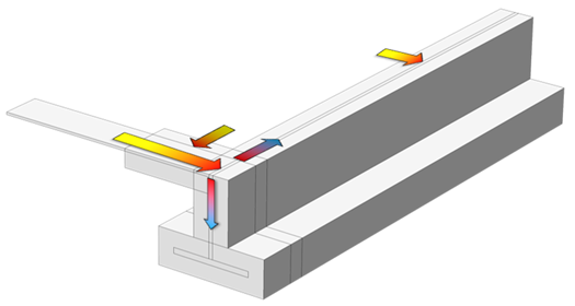
Figure 2: heat paths around a connection with a coat back (one half of a symmetric geometry modelled)
Considerations for a simplified model
The starting point for the model is the need to simplify as much as possible the full three-dimensional geometry of the cross-section, without compromising on the key geometric features that are governing the local heating of the primary member at the location of the attachment connection:
- Cross-section area, exposed perimeter and section factor of the primary member,
- Cross-section area, exposed perimeter and section factor of the attachment,
- Number of attachments connecting to one location on the primary member,
- Fire protection thickness and properties,
- Fire exposure time.
Starting with the most simple model available, one could try to calculate this in a “zero dimensional” model, where the steel mass is considered as one point and the fire protection as a certain delaying factor for the heat to reach the steel. This does not provide any credible answer because the different heat paths are not included and also the heat sink of the steel mass would depend for example on the (a priori unknown) length of the primary member that is influenced by the heat flow through the attachment.
One step more advanced, a one-dimensional model is pretty accurate for the modelling of temperatures in fireproofed linear steel sections. The thickness of the fireproofing is explicitly modelled, and the modelled thickness of the steel determines the heat sink and is therefore directly linked to the section factor of the steel member. However, the limitations with regard to the heat paths and the length of the influence zone are the same as for the zero-dimensional model.
With a two-dimensional model, a larger number of relevant effects can be included:
- The thickness (i.e. inverse of the section factor) of the primary member,
- The thickness of the passive fire protection on the primary member,
- The thickness (i.e. inverse of the section factor) of the attachment,
- The thickness of the passive fire protection on the attachment,
- The length of the coat back.
The two-dimensional model comes closer to reality, but it fails to include the actual cross section areas of the primary member and the attachment.
A Semi-3D model
In order to have all the benefits of the two-dimensional model and to also include the cross section areas of the primary member and the attachment, the two-dimensional model is expanded with a third dimension in the form of a certain thickness.
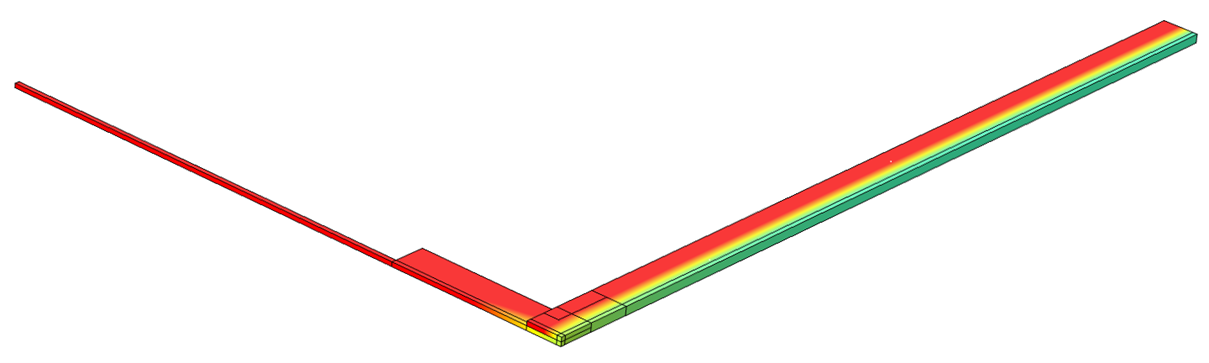
Figure 3: the Semi-3D model. A two-dimensional model with a thickness.
In this way, the thickness of the primary member and the attachment can be varied independently. The thickness represents the perimeter of the section that is exposed to fire. This perimeter is equal to the section factor multiplied by the cross section area. It is the ratio of the exposed perimeters of the primary beam and the attachment that influences the temperatures of the connection. Therefore, the thickness of the primary member can be arbitrarily chosen at any value, as long as the thickness of the attachment is in the correct proportion to it. For example if the exposed perimeter of the primary member is 1000mm and the perimeter of the attachment is 200mm, in the model one could choose to set the thickness of the primary member at (arbitrarily) 10mm and the thickness of the attachment at 2mm.
The translation of the full cross section into a semi-3D cross section is illustrated below.
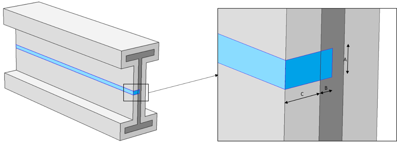
Figure 4: 3D section translated into a semi-3D section: in the 2D plane, B represents the average steel thickness (i.e. inverse of the section factor), C represents the fire protection thickness. In the third direction, A represents the (proportional) exposed perimeter.
The model was developed using the following input parameters and material properties:
- The hydrocarbon fire curve as given in UL1709 (“rapid rise fire”) was used, as this is slightly more onerous than the hydrocarbon fire curve given in EN 1363-2,
- Temperature dependent thermal properties of the passive fire protection, calibrated with fire test data following e.g. BS, UL and EN test standards with hydrocarbon fire curves,
- Temperature dependent thermal properties of steel in accordance with EN 1993-1-2.
Corner connection detail
When developing the Semi-3D model, it appeared that the modelling of the heat transfer in the corner has a major influence on the calculated steel temperatures at the attachment / primary member connection.
A solution was found in applying a thermal disconnection between the part of the perimeter of the primary member that was directly exposed to fire and the part that was shielded by the attachment and its fire protection forming a local corner. This is realistic, as in practice the shielding effect will also be greater if the attachment has a larger perimeter and therefore covers a larger part of the primary member.
Validation
29 cases were fully modelled in 3D, in order to have a relevant benchmark for the simple model. The cases systematically cover a number of aspects:
- High to low section factor for primary members
- High to low section factor for attachments
- Attachments of different sizes (exposed perimeters)
- Attachment connection to the flange or the web
- Single attachments (asymmetric) or double attachments (symmetric)
- Shape (H-section or flat strip) and orientation of the attachment
- Varying coat back lengths
- Varying passive fire protection thicknesses
Each of the cases that were fully modelled in 3D was also modelled using the Semi-3D model, resulting in a graph showing three temperature lines:
- Full 3D model: maximum local temperature of the primary member at the location of the attachment connection,
- Full 3D model: average cross section temperature of the primary member at the location of the attachment connection,
- Semi-3D model: temperature of the primary member at the location of the attachment connection.
An example of a validation graph is shown below.
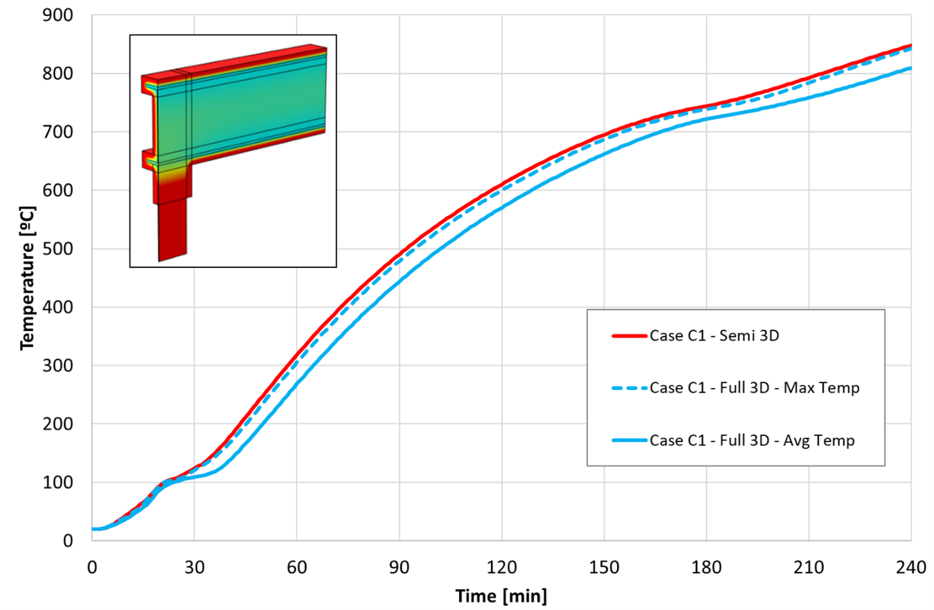
Figure 5: typical validation graph. In this case (blue lines), a strip is attached to one flange of an H-section, compared to the temperatures calculated with the Semi-3D model (red line).
As can be seen from this figure, the Semi-3D model closely follows the maximum cross section temperatures as calculated in the full 3D model, and is slightly on the conservative side.
Only when the attachment is fixed to the web, in some cases the maximum temperature of the web is slightly (typically 30oC) higher than predicted by the Semi-3D model. This is however always a very local effect and it is accompanied by an average cross section temperature that is lower than predicted by the Semi-3D model (typically 50oC lower for the average of the full cross section, i.e. including the hot zone of the web). From a structural point of view, the locally higher temperature is more than compensated by the much lower flange temperatures and is unlikely to cause structural failure.
When the attachment is connected to the flanges, the Semi-3D model generally slightly overpredicts even the maximum temperatures calculated in the full 3D simulations.
It was also observed that the model becomes more conservative when the coat back length is reduced. This means that when the model is used to optimise the shortest possible coat back length to fulfil the requirements, it is especially conservative.
Scope and limitations
The Semi-3D model captures all the relevant properties for the calculation of the heat flow, except for heat path 6. The validation study however demonstrated that the model is conservative. The model assumes that there is no overlap between the influence zones of two adjacent attachments. Certainly if sufficient coat back is applied, this assumption will be correct.
Boxed vs. profiled protection
The model is only valid for profiled fire protection. In case of boxed fire protection, thermal transfer by convection and radiation through the hollow areas can change the behaviour. By definition, the Semi-3D model is not suitable to include hollow areas. A practical solution to eliminate heat flow by convection and radiation is to fill up the hollow areas with a heat resistant material. In that case, the model is again conservative.
Three vs. four sided protection
Leaving the top of a steel beam unprotected is a common practice in the Oil & Gas sector. However from a fire design perspective, this causes a major reduction of the fire resistance. Separate simulations (not presented in this paper) show that if a beam is exposed to a hydrocarbon fire curve with the top flange unprotected, the critical steel temperature is already exceeded within 5 to 10 minutes. This occurs irrespective of the intended fire rating and corresponding fire protection thickness on the three protected sides. Even under the optimistic assumption that much lower fire temperatures impact the top of the beam, still there is a strong reduction of the fire resistance. When passive fire protection systems are fire tested in a three sided configuration, there is always a concrete or autoclaved aerated concrete floor on top of the beam that protects the top against fire. This is essential to reach the required fire resistance.
This issue is however unrelated to the additional local heating caused by attachments and the need for coat backs. Under the assumption that in a three sided configuration also the top of the beam is shielded from the fire, the Semi-3D model is equally valid. The model is therefore valid for beams and columns and for exposure on three or four sides, as all these variations are expressed in the section factors and exposed perimeters.
Structural nodes, multiple attachments
As the Semi-3D model represents one quarter of a symmetric situation, by default it calculates the heat flow for a situation where attachments are connected opposite each other on either side of the primary member. However by adjusting the exposed perimeter of the attachment, the model can be equally used for single attachments or for more than two attachments located at the same structural node. This was confirmed by calculating full 3D validation cases with multiple attachments.
Conclusion
Omitting coat backs significantly reduces the time to reach the critical steel temperature. An indicative parameter study within practical ranges showed that the critical steel temperature is reached roughly 20% to 80% sooner if coat backs are omitted. In other words, protecting a beam for 120 minutes fire resistance but not applying coat backs may result in an actual fire resistance between roughly 24 and 96 minutes. For this reason it is strongly recommended to apply coat backs. With the Semi-3D model it has now become possible to quickly determine the required coat back lengths for a wide range of geometries. The model is validated with full three-dimensional thermal finite element calculations, for steel protected by passive fire protection systems and exposed to hydrocarbon fire curves. For all modelling work the steel properties were in accordance with EN 1993-1-2 and the properties of the passive fire protection material were calibrated to be conservative for a large number of fire tests on steel elements protected with a specific passive fire protection system.
Acknowledgement
The author wishes to thank Dr Enrique Munoz-Garcia of MMI Thornton Tomasetti for his review comments. This article is a compact version of an article published by PFPNet (https://www.pfpnet.com/wp-content/uploads/2019/02/Coat-Back-Lengths-PROMAT-Paper.pdf).