UK Case Study - 15 Old Bailey Hotel, London
By: Karl Wallasch, Trigon Fire Safety, UK
1. Introduction
15 Old Bailey was originally built in 1874 and formerly home to the first London Hotel with electrical light. The building, located close to St Paul’s and City Thameslink Stations and on the same street as The Central Criminal Court of England and Wales (also commonly known as ‘The Old Bailey’), was then used as a serviced office building and reopened as a hotel in autumn 2024. The project development of this Grade II listed building included a general refurbishment, extension and change of use to a luxury hotel. Today, the hotel is operated by Ennismore and includes a total of 110 bedrooms, a fitness centre, a full-service restaurant and speakeasy bar at basement level. The height of the top storey (seventh floor level) is 24 m.
This article describes the key fire safety features that form part of the fire safety strategy for the new hotel. This strategy considered how to meet legislative requirements while supporting the architectural vision, heritage and space restrictions, and the economic constraints of the project. Specific focus is given to the application of computational fluid dynamics (CFD) modelling as part of the smoke shaft design for the new firefighting shaft.
2. Fire Safety Strategy Overview
The client appointed a team of fire safety engineers right from the initial feasibility study for the project, and then throughout the concept and detailed design stages, as well as construction. As part of this service, the fire safety engineers supported the design team with several mark-ups, sketches, and technical notes comparing different design options, and a detailed fire safety strategy report suitable for Approval Authorities review.
The key fire safety elements are listed below in Table 1.
Table 1: Key fire safety elements
|
Item
|
Comment
|
|
Legislation / Guidance:
|
Building Regulations 2010 [4] / Approved Document B, Volume 2 [2]
|
|
Evacuation type:
|
Simultaneous evacuation
|
|
Fire detection:
|
Automatic fire detection and alarm as well as manual call points
|
|
No and type of stairs:
|
One escape stair and one firefighting stair
|
|
Elements of structure:
|
90 minutes of fire resistance due to a height of more than 18 m, but less than 30 m
|
|
Compartment floors:
|
90 minutes of fire resistance
|
|
Hotel room corridors:
|
30 minutes of fire resistance
|
|
Suppression system:
|
Water mist system (in the basement level only)
|
|
Basement smoke ventilation:
|
Mechanical smoke ventilation achieving at least 10 air changes per hour
|
|
Fire service access:
|
Via a firefighting shaft (FFS) due to the building's height; including firefighter lift and dry riser
|
|
Ventilation to FFS:
|
Mechanical smoke extract shaft in firefighting lobby and automatic openable vent (AOV) at head of stair
|
3. Smoke Ventilation system of Firefighting Shaft
ADB recommends that a firefighting stair and a firefighter’s lift should be approached from the accommodation through a firefighting lobby. For firefighting shafts, ADB refers to the guidance in BS 9999 [2]. Both the firefighting stair and lobby should be provided with a means of venting smoke and heat by following clause 27.1 of BS 9999. As per this clause, firefighting lobbies should be provided with smoke control systems by means of either a pressure differential system, a mechanical smoke ventilation system, or a natural smoke ventilation system.
A firefighting shaft was not present in the existing building, and the design and installation within the existing building required a unique approach
Therefore the proposal for this project was to provide a mechanical smoke extract system to serve the firefighting lobbies at basement, ground, and first to sixth floor levels, with smoke extraction at ground floor level via the external wall onto Green Arbour Street. The extract location would typically be located at roof level, so that smoke is extracted upwards, however, due to space restrictions this was not a feasible option. The proposal for the seventh floor was to allow for natural smoke ventilation in the lobby via an opening to roof level.
In accordance with standard guidance, where mechanical smoke extract is being used, the system should be designed to demonstrate equivalent or better conditions in the stair than would be provided by a natural smoke shaft solution conforming to the recommendations of BS 9999 and as described in BRE project Report 79204 [3]. BS 9999 states that the primary objective of the system should be to maintain smoke-free conditions in the staircase during both means of escape and firefighting operations. It is therefore considered that the key criteria for acceptance should be that the conditions are no worse in the stair enclosure.
4. CFD Modelling
4.1. General
In order to provide a comparative study between the proposed mechanical system and a natural solution, designed in line with the recommendations of BS 9999, the performance of both systems was evaluated using CFD modelling. Provided the agreed model demonstrated an equivalent, or better, performance compared to the natural solution, it was considered to meet the functional requirements of the Building Regulations 2010.
Solution 1: Natural Smoke Shaft
BS 9999 provides a number of recommendations for venting of firefighting shafts by natural means. The following provisions were adopted for the above ground smoke shaft solution:
· Free area of smoke shaft: 3.0 m2, with dimensions 1.0 m x 3.0 m.
· Lobby vent into the smoke shaft will be located as close to the ceiling as practicable as per the recommendations above, and will achieve an aerodynamic free area of 2.0 m2, with dimension 2.0 m x 1.0 m.
· Lobby vent to open upon the detection of smoke in the corridor.
· Automatic opening vent (AOV) will be provided at the head of the shaft achieving an aerodynamic free area of 2.0 m2 (actuation simultaneously with the lobby vent into the smoke shaft, upon the detection of smoke in the common bedroom corridor).
Solution 2: Mechanical Smoke Shaft
The mechanical smoke extract system has been provided with 'lobby vents’ between the mechanical extract shaft and the lobbies at each floor level. The lobby vents were located as close to the ceiling as is practicable and at least as high as the top of the door connecting the lobby to the stair well. Upon the detection of smoke in the common corridor, the lobby vent, head of stair vent, and fans associated with the mechanical smoke extract system has been actuate, initiating the ventilation afforded to the protected lobby. The lobby has been provided with a pressure flow switch, designed to vary the extract rate of the mechanical smoke extract system based on the pressure detected in the firefighting lobby.
Unlike a typical smoke extract system, the proposed system was designed to discharge smoke via the external wall at lower level as opposed to discharging the smoke upwards and at roof level. This is due to the constraints created by the existing structure and limited plant space at roof level. Therefore, the fan was located at the mezzanine level between the ground and first floors.
A number of considerations played an important role in the CFD modelling:
· Fire scenarios and locations: fire locations at sixth floor level, first floor, and basement level.
· Reasonable worst case fire scenarios: worst case during means of escape phase as well as firefighting phase.
· Software: Fire Dynamics Simulator (FDS) by National Institute of Standards and Technology (NIST) Version 6 [5].
· Cell sizes: 10 cm x 10 cm x 10 cm
· Leakage rate through doors and lifts: vary between 0.01 – 0.02 m2
· Door opening and closing scenario depended on the scenario considered i.e., means of escape or firefighting access.
· Fire size: 4 m2 fire size with 500 kW/m2 resulting in 2 MW fire (steady state). Modelling a steady state 2 MW fire allows a direct comparison to be drawn between the proposed mechanical smoke ventilation strategy and the natural smoke ventilation solution designed in accordance with BS 9999.
4.2 Overview of Results
After completion of the CFD modelling, the following were provided as graphs, figures, and description in the CFD modelling report, throughout both the means of escape and firefighting phases:
· Review of Heat release rate for each fire scenario;
· Review of visibility (m) changes in stair, lobby and corridor;
· Review of temperature (°C) changes in stair, lobby and corridor;
· Review of pressure (Pa) changes in fire room, stair, lobby and corridor; and
· Air / smoke spread and movement in fire room, firefighting stair, firefighting lobby, corridor, and smoke shaft.
The results demonstrated that the proposed mechanical extract system, performs at least similar to if not better than a natural ventilation system designed in accordance with the recommendations of BS 9999, during both the means of escape and firefighting phases.
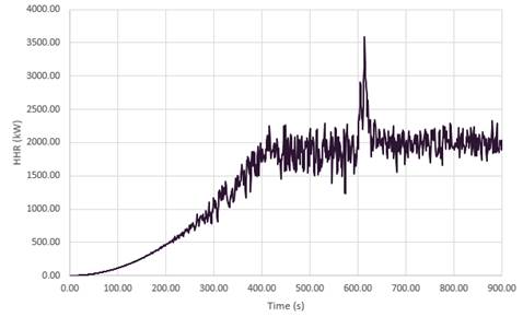
Figure 1: Example of typical heat release rate development over time.
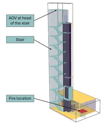
Figure 2: 3D-Geometry used in CFD modelling – Fire location at First Floor.

Figure 3: Temperature slice (blue = 20°C; red = >110°C) – Horizontal Section at First Floor.
5. Approval Process
As part of the approval process, the Building Control body involved an independent third-party reviewer for the aspect of the CFD modelling. The design team engaged with both at an early stage of the development of the initial fire safety when it was identified that fire engineering (in form of CFD modelling) would be applied. Detailed discussion took place about the proposed approach, methodology, and general assumptions to be used in the CFD modelling study. Only after agreeing on the approach and key parameters, was the detailed CFD modelling conducted. After completing the CFD modelling and report, further discussions with Building Control took place. Detailed discussions led to a comprehensive final report for Building Regulations approval.
These discussions contributed to a comprehensive and robust final report, agreed and coordinated with all stakeholders, and which then formed part of the information package submitted for Building Regulations approval, including consultation with London Fire Brigade (LFB). The report also formed part of the information package provided to building manager.
6. Conclusions
A fire safety strategy was developed for the proposed change of use of 15 Old Bailey to a luxury hotel. As part of the fire safety strategy, CFD modelling was used to demonstrate that the proposed design of the unique mechanical smoke extract solution as part of the firefighting shaft design meets the functional requirements of the Building Regulations. The CFD modelling conducted demonstrated that the proposed mechanical ventilation solution performs not only equal to, but in this case better than, a standard natural ventilation solution.
This case study demonstrates how fire engineering, when carefully considered and coordinated at early stage with all relevant stakeholders, including third-party reviewers, can support design aspirations and constraints, as well as manage and remove risks of non-approval.
7. References
[1] Approved Document B: Fire Safety – Volume 2: Buildings other than dwellings, 2019 edition. The Stationery Office Limited. 2019 (with May 2020 amendments).
[2] BS 9999: 2017, Fire safety in the design, management and use of buildings - Code of practice. British Standard Institution (BSI) Global, 2017.
[3] BRE project Report 79204: Smoke shafts protecting fire fighting shafts: their performance and design, Building Research Establishment, 2002.
[4] Building Regulations 2010, Her Majesty’s Stationery Office (HMSO), England and Wales. September 2010.
[5] Fire Dynamics Simulator (FDS) by National Institute of Standards and Technology (NIST) Version 6, www.pages.nist.gov/fds-smv
[6] The SFPE Guide to Performance-Based Fire Safety Design, by SFPE (Society of Protection Engineers), Published 2015: www.sfpe.org/publications/resources/pbdguide
[7] CIBSE Guide E – Fire safety engineering, Fourth edition, June 2019, The Chartered Institution of Building Services Engineers, London.