
View the PDF here
Data transfer at the speed of light, but is it reliable in a fire?
By: Joakim Åström and Sofia Lindahl, Students at Lund University, Sweden.
Data transfer have almost exclusively been done through electrical cables, but the use of fibre optic cables is increasing. Is a fibre optic cable transferring data with the same quality as an electrical cable? As it turns out the fibre optic cable might be the better choice.
Sometimes the communication between devices is taken for granted. Take an ordinary light switch for example. When you flip the switch, the light comes on, this is due to electricity being transported along a cable to the light bulb. Much the same happens when we control more advanced equipment that carry out actions, such as closing a valve, instead of bringing light to your kitchen. Sometimes there are situations at which this action is absolutely critical to the safety of humans, for example in a nuclear power plant.
In these types of facilities, the actions need to be carried out from a distance and that is where the cables come in. In case of an emergency the cables need to work. This can be shown through a real example, the Browns Ferry Nuclear Power Plant accident in March 1975 [1]. A fire damaged 1600 cables, where 600 of these were cables that monitored or controlled safety features of the plant. The damages to the cables caused several faults to occur; some safety features could no longer be operated from a distance, some safety features were put into motion by themselves, and some instruments on the control panel showed misleading indications [1].
The misleading and erroneous signals in the Browns Ferry accident was probably due to the use of electrical cables for control equipment. In other words, there was a possibility for the signal to go the wrong way if the cables came in contact with each other. Signals that are interpreted by computers have mainly been sent using electricity, but it is also possible to use light to send the same signals through fibre optic cables. The fibre optic cables offer higher speed as well as an inherent electrical isolation. With fibre optic cables, the problem with signals going the wrong way becomes impossible as they themselves are electrically insulated. Instead, the problem with a fibre optic cable subjected to fire is how the light being transmitted is disturbed, and thus the actual data can be affected. This problem was identified by the European Spallation Source (ESS) and a master thesis was conducted on how fire conditions affect the attenuation through a fibre optic cable [2]. However, this attenuation could not be translated to a loss of data. To further investigate fibre optic cables’ behaviour during fire a recent master thesis, that includes of an experimental study, has been conducted. This master thesis [3] investigated how data transfer is affected and an effort to create a probabilistic distribution was made. However, some of the technical aspects as well as the experimental setup will first be described.
Fibre optics and data transfer
In a fibre optic cable, a wave of light is guided through a core made of clear glass. Surrounding the core is something called cladding which is glass that is less refractive [4]. When the light hits the cladding, it bounces back into the core and continues forward [4]. As the wave of light propagate through the cable the amplitude and intensity decrease along the way, and this is called attenuation [5]. The amplitude decreases over a distance and can be explained by Figure 1. The original data signal is a pattern of on and off (up and down), as the light propagates the difference between on and off decrease and finally the signal can no longer be interpreted.

Figure 1. Decrease in amplitude of the light. Top, outgoing signal. Bottom, signal being
stretched out due to attenuation, with the original shape for illustrative purposes.
The other part of attenuation is the loss of intensity, or loss of photons in the wave of light. This is a result of mainly three different properties: absorption, scattering and leakage (radiation) [4, 6]. In short, absorption is when light is absorbed into the molecules of the fibre. Scattering is a combination of light hitting the molecules as well as impurities in the fibre, and leakage is light that escape out from the core and cladding. As a cable is bent or mismanaged, cracks can form which leads to an increase in leakage. One study has been made on tensile strength of fibres from fibre optic cables, the result of this was that the strength decreased with increasing temperature [7]. If the tensile strength decreases, the fibre will start to crack even more, and more light can be lost due to leakage.
The signal needs to be interpreted by a computer as ones and zeros, in other words as a digital signal [4, 5]. Disturbance in the signal due to loss of light or other disturbance can have effects on the end result, for example if the data loss is too large some computer systems can shut down or in other ways malfunction [8]. Regardless if data is sent through light or electricity there needs to be a unified set of rules, called protocols, for the sending and receiving computer to interpret the signal [9]. These protocols create data packages, clusters of ones and zeros, that can be measured.
Sample holder and test setup
In the recent master thesis project [3] a sample holder for the cable was constructed based on previously conducted experiments and details from two standards on cable testing. In the IEC 60331-25:1999 standard, the cable is suspended in the air by resting on metallic rings [10], and in the SS-EN 50200:2006 standard, the cable is mounted in a U-shape on a non-combustible board [11]. Both these details were incorporated in the thesis work by having the cable suspended in the air in a U-shape with a non-combustible board under the cable. A pendulum was also installed to strike the sample holder every 10 minutes and the details for the pendulum was incorporated from the SS-EN 50200:2006 standard [11]. The cables were installed in the sample holder with the smallest bend diameter recommended by the manufacturer. The sample holder can be seen in Figure 2, where the yellow marking indicates where the pendulum struck the sample holder.
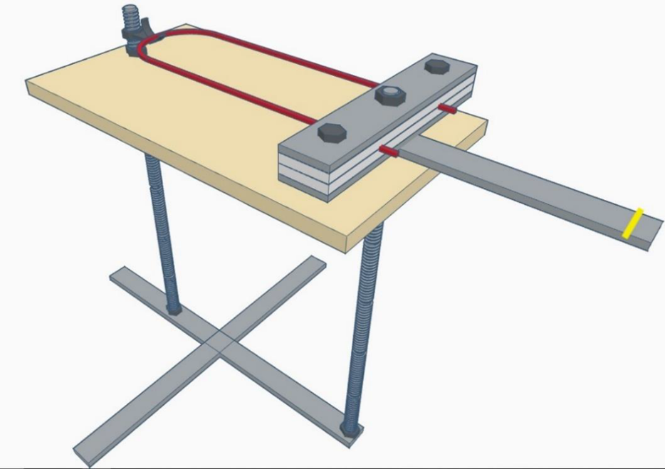
Figure 2. Sample holder setup.
During the tests, a cable was gradually exposed to an increasing heat flux from a cone calorimeter [12]. In the tests, the heat flux started at 15 kW/m2 and was increased to 25 kW/m2 after 10 minutes, 35 kW/m2 after another 10 minutes, and finally 50 kW/m2 after another 10 minutes. After 30 minutes the heat flux was at the maximum value for the experiment and remained at 50 kW/m2 until the cable could no longer transfer data or until 90 minutes of the test had passed. The cables that were used for these tests were single-mode cables with one fibre. These cables were chosen because the goal was to examine the functionality of the cable, with as little protection as possible. A picture of a test cable mounted in the sample holder can be seen in Figure 3. In addition, SM cables are becoming more common than MM cables. Since the goal was to measure data loss, a local area network (LAN) was created between two computers. The data was then transferred from one computer to another, where bandwidth and data loss for the transferred data was measured continuously.
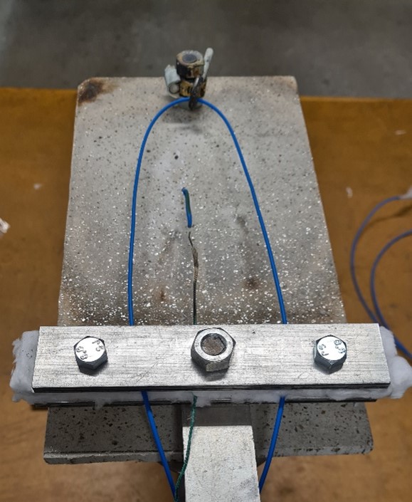
Figure 3. Cable mounted in the sample holder.
Results and conclusions
The tests resulted in zero data loss until the cable broke or the test was terminated after 90 minutes. The conditions for breaking of the cable were shown to be a relationship between temperature and mechanical strain from smaller bend diameter created by the fibre moving due to thermal influence. For those tests that led to a break in the cone calorimeter, temperatures of 400 – 600 ºC were measured. Besides measured data, such as data loss and temperature, the cables were also visually examined and interesting events were timed to help draw conclusions. With the temperature measurements at the time of break, a data analysis was made where a probabilistic distribution for temperature at the time of break was fitted.
A couple of conclusions could be drawn from the tests and they are presented below:
- The signal in a single-mode fibre shows resilience to fire exposure.
- Based on this study, a probabilistic distribution of the critical temperature resulted in a 5th percentile of 336 ºC, i.e., 95% of the cables have a critical temperature above 336 ºC.
- Even if installed according to the manufacturer’s recommendations, bends that lead to break can be formed on the cable due to thermal stresses.
- Fibre optic cables have inherent properties such as electrical isolation which makes them useful for critical safety systems in, for example, high reliability facilities.
References
[1] Åslund, Alf. Säkerhetsrelaterade systemkomponenters felmoder vid brand på kärnkraftverk. Stockholm: SwedPower AB, 2000.
[2] Rosenqvist, Jonathan. Fiber optics communication failure modes. Lund: Department of Fire Safety Engineering, Lund University, 2014.
[3] Åström, Joakim and Lindahl, Sofia. Damage Criteria for Fibre Optic Cables Exposed to Fire - Using data transfer as functional criterium. Lund: Division of Fire Safety Engineering, Faculty of Engineering, Lund University, 2021.
[4] Hecht, Jeff. Understanding Fiber Optics. Auburndale, Massachusetts: LaserLight Press, 2006.
[5] Wright, Edwin and Bailey, David. Practical Fiber Optics. Newnes, 2003.
[6] Hui, Rongqing. Fiber optic measurement techniques. San Diego, California: Academic Press, Inc., 2009.
[7] Tu, Yun and Tu, S.-T. Tensile strength of silica optical fibers for high-temperature sensing applications. [book auth.] Lin Ye. Recent Advances in Structural Integrity Analysis - Proceedings of the International Congress. Woodhead Publishing, 2014, pp. 158-162.
[8] DeCusatis, Casimer. Optical Link Budgets. Handbook of Fiber Optic Data Communication. San Diego, California: Academic Press, Inc., 2014, pp. 55-76.
[9] Loshin, Peter. TCP/IP clearly explained. San Franciso, California: Morgan Kaufmann Publishers Inc., 2003.
[10] IEC. IEC 60331-25:1999 - Tests for electric cables under fire conditions – Circuit integrity – Part 25: Procedures and requirements – Optical fibre cables. Geneva: International Electrotechnical Commission, 1999.
[11] SEK. SS-EN 50200:2006 - Method of test for resistance to fire of unprotected small cables for use in emergency circuits. Stockholm: Svensk Elstandard, 2006.
[12] SIS. SS-ISO 5660-1:2019 - Reaction-to-fire tests – Heat release, smoke production and mass loss rate – Part 1: Heat release rate (cone calorimeter method) and smoke production rate (dynamic measurement) (ISO 5660‑1:2015, IDT). Stockholm: Swedish Standards Institute, 2019.